Switches | Outlets & Plugs | Ballasts | Replace Ballasts | LED Tube Lights | Troubleshooting | Basic Electricity | Misc Articles
Multi-Wire Branch Circuits
A multi-
- The black wire is usually the A phase 120V.
- The red wire is usually the B phase 120V.
- The white wire is the neutral, providing return current for both of the A and B phase 120V.
- The bare copper wire is the ground.
See example diagrams below. Outlet ground connection diagram shown separately.
Multi-Wire Branch Circuit Wiring Diagrams
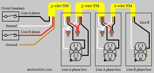
Multi-Wire Branch Circuit Correct Wiring Diagram
The neutral wires are connected together before connecting to the terminals on the left outlet. The NEC does not require the line (black) wires to be connected together before connecting to the terminals on the left outlet.
It is preferred that the line (black) wires be connected together before connecting to the terminals on the left outlet, even though it is not required by the NEC.
Multi-Wire Branch Circuit Incorrect Wiring
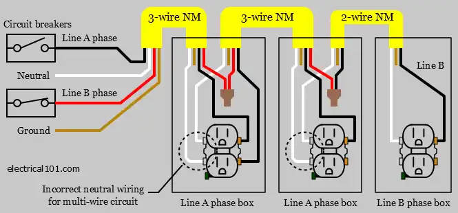
The neutral wires are not connected together before connecting to the outlet on the left. The two left outlets do not meet the NEC for a multi-
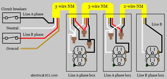
Multi-Wire Branch Circuit Preferred Wiring Diagram
Multi-
About Privacy Policy Sitemap Copyright © 2024 Electrical101.com Terms of Use